Prelab
The following is a wiring diagram that I used for this lab:
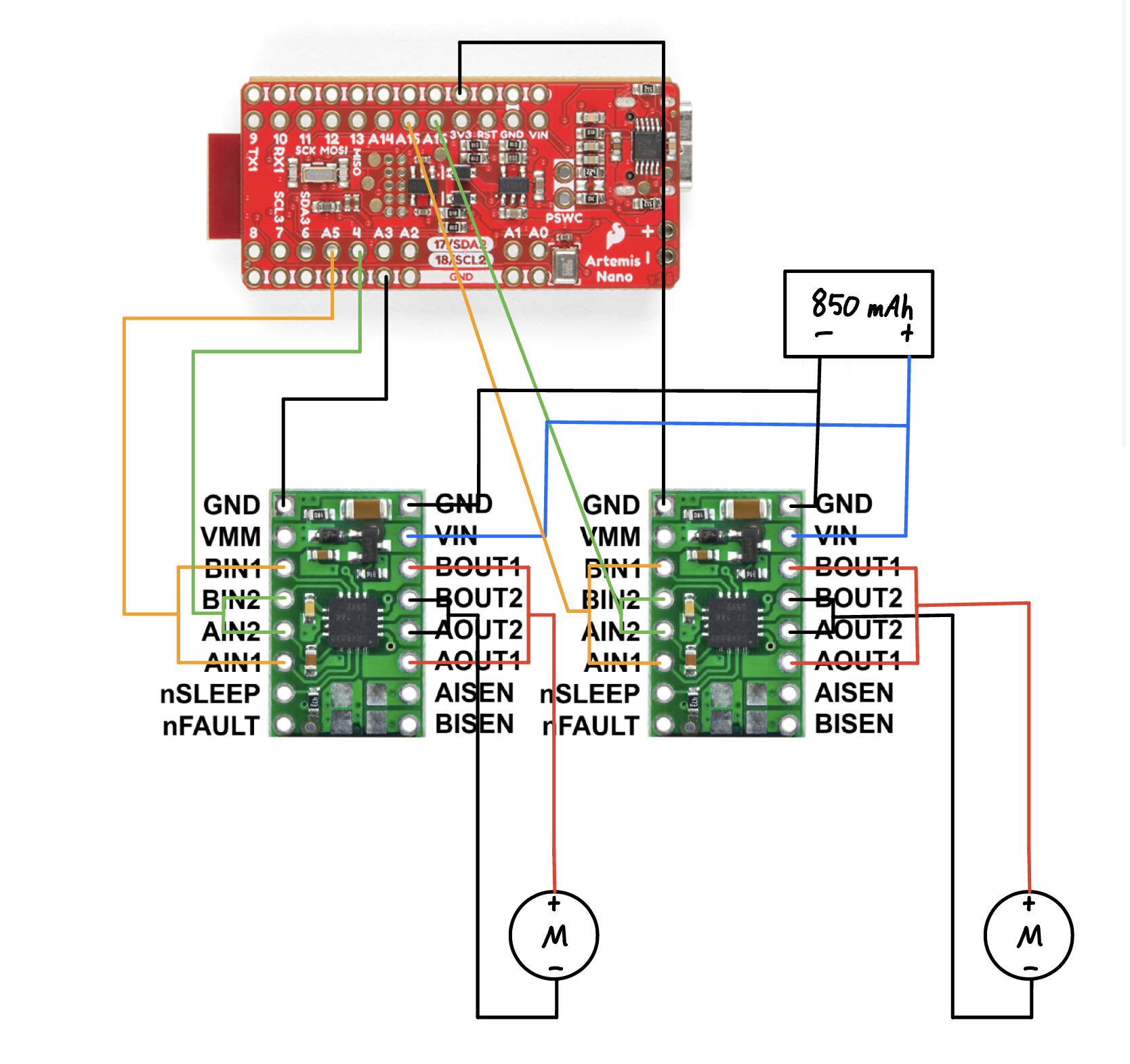
An important observation from the wiring diagram is that each motor is being driven by a single dual motor driver. So each motor driver actually has two input pins and two output pins. Normally, you would connect one input-output pair to one motor. But for this lab, to get as much power out of the motor driver as possible and deliver it to a single motor, we short the two inputs and two output pins together. Even though the voltage supplied to the motor is the same, we are essentially doubling the current, thereby doubling the power delivered to each motor.
I used pins 4, A5, A15, A16 as inputs to the motor drivers because they have PWM capability as per the pinout diagram of the Artemis Nano.
I powered the Artemis and the motor drivers using separate batteries. This is because the motor drivers use significantly more power than the Artemis so it would make sense to allocate a more powerful battery to the motor drivers.
Lab Tasks
I hooked up the motor drivers to the Artemis as well as the motors to the motor drivers and tested that the output signals of the motor drivers were PWM signals. Here is a picture of the setup for measuring the output signals:
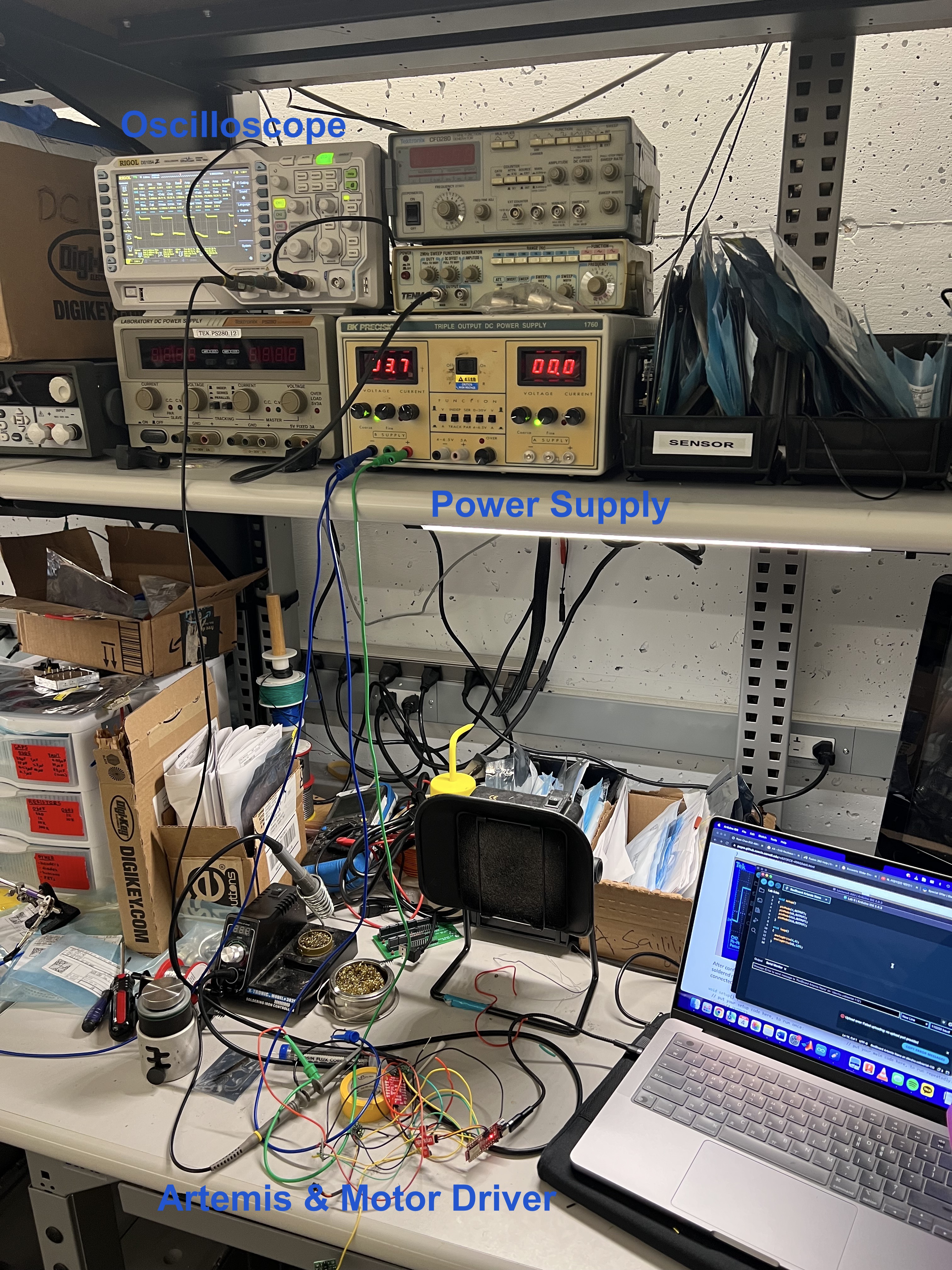
Because the motor driver uses a 3.7 V battery, I set the power supply to 3.7 V. The code I used to test the PWM signal is the following:
Here is the actual output displayed on the oscilloscope:
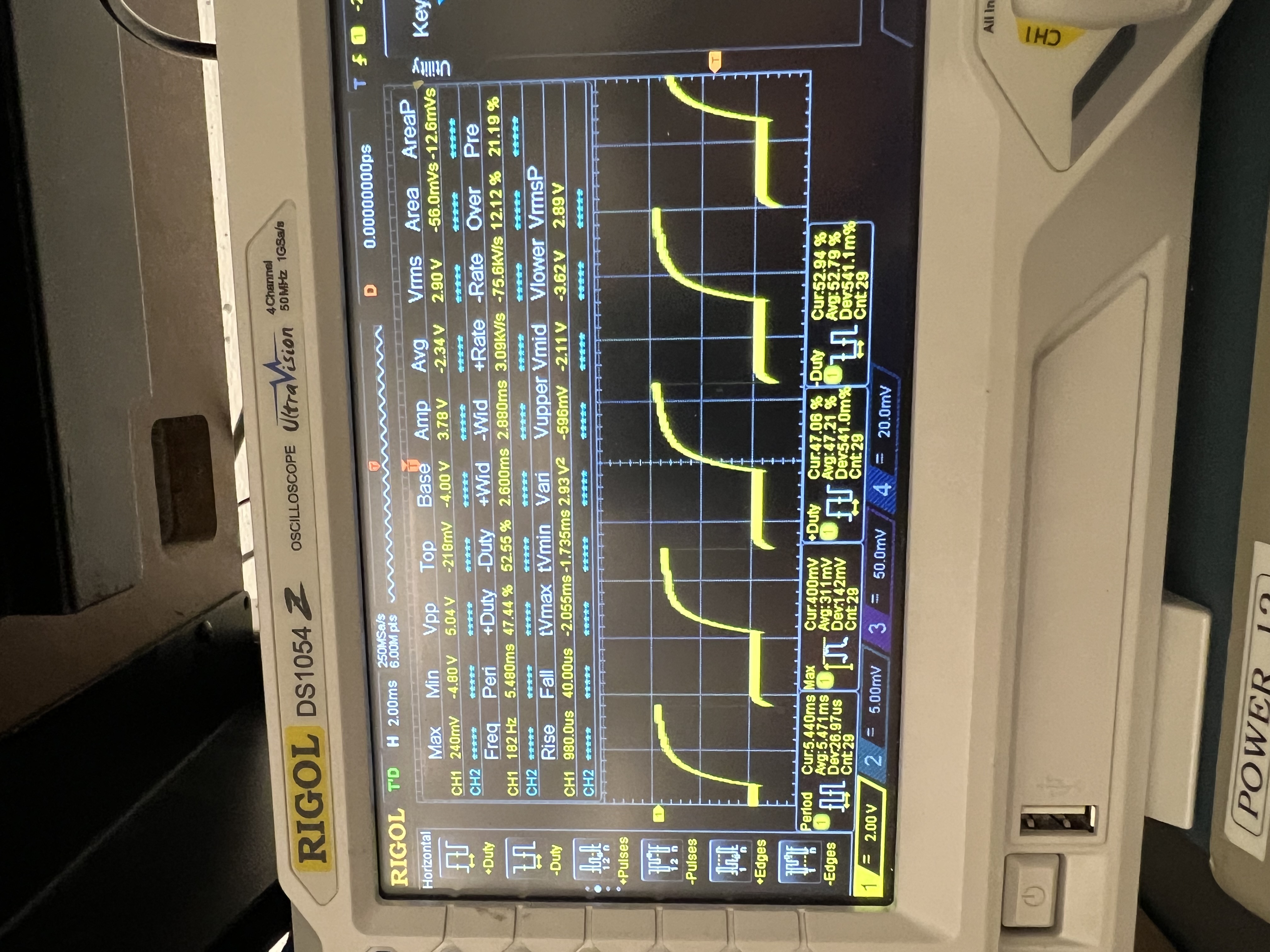
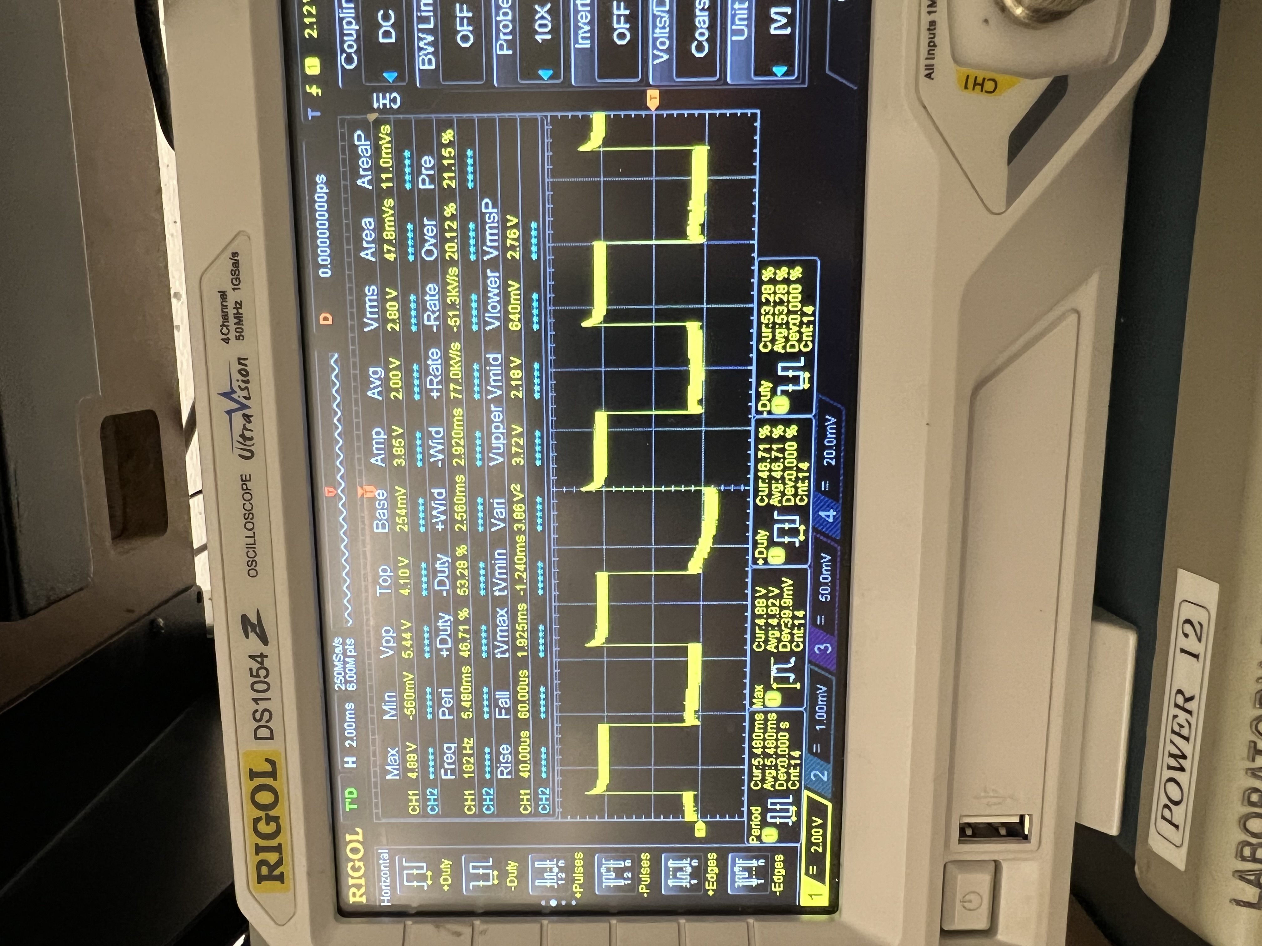
The first image corresponds to the motor spinning forwards and the second image corresponds to the motor spinning backwards.
Knowing that the motor drivers indeed output proper PWM signals, I finally hooked up the GND and VIN pins on the motor drivers to the battery. Here is are pictures of before and after wiring everything together:
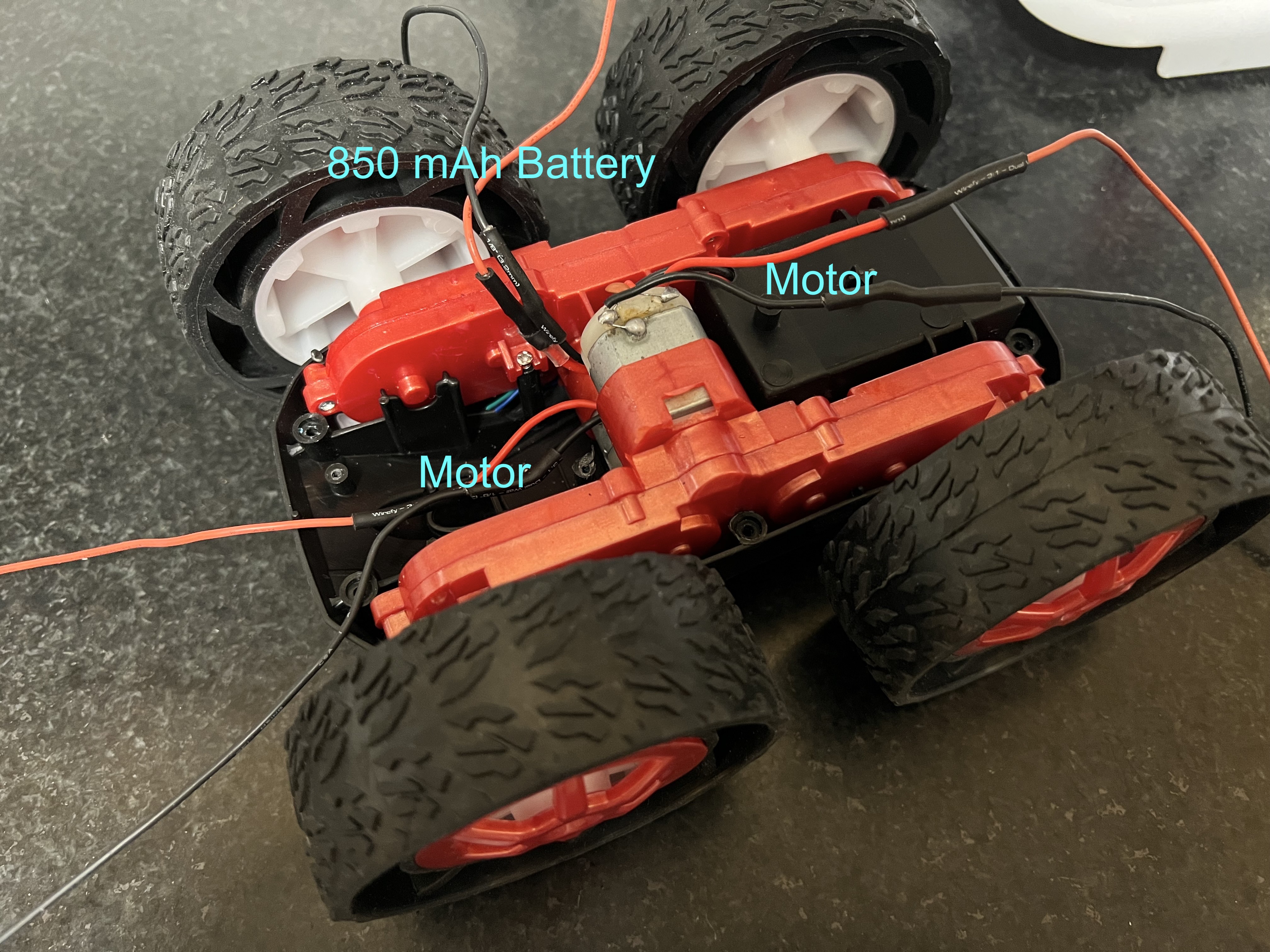
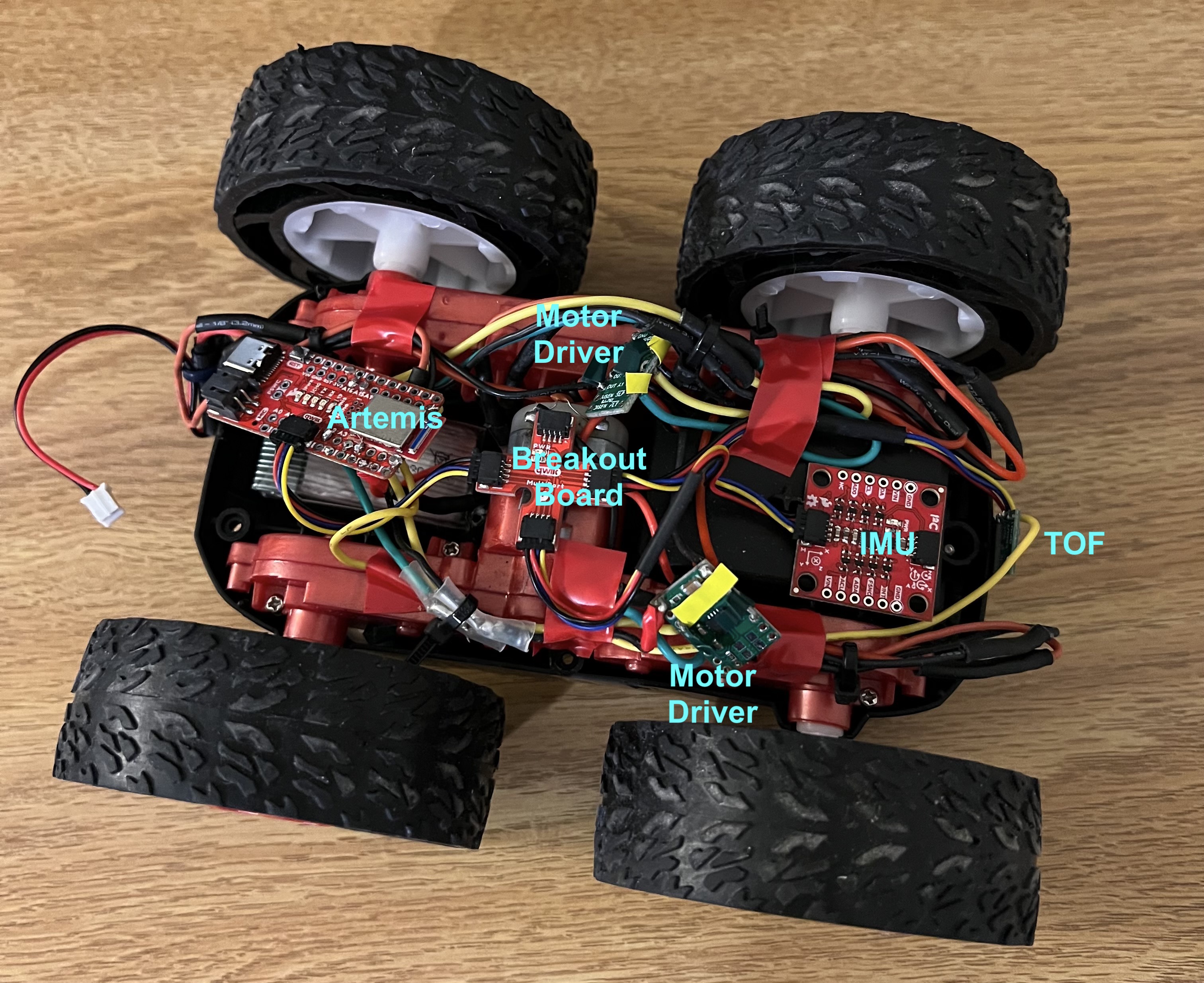
I used the following code to test that both wheels spin:
The following is a video showing that the motors do indeed spin:
To find the lowest duty cycle that can actually make the car move (i.e. overcome static friction in the wheel bearings), I started at a duty cycle of 10/255 and incrementally increased it by 10/255 each time. The lowest duty cycle that made the car move was 40/255.
For the motors, no calibration was needed as the car moved straight when both motors were given the PWM signals with duty cycle equal to 120/255. Here is a video of the car moving straight for at least 2m:
But the car does start to steer off as the distance increases.
Next, I wrote code to demonstrate open loop control that drives the car forward, turns, drives it backwards, and turns again. Here is the code for this open loop control:
Here is a video of running this code on the car: