Recap
In labs 1, 3-5, I built a working robot capabale of moving and sensing distance + orientation. In lab 2, I implemented debugging capabilities using BLE (bluetooth). In labs 6-8, I implemented closed loop control to get the robot to move a certain distance and rotate by a certain angle. In labs 9-11, the robot learned to map its environment and localize itself within it. Using all of these features, the goal of lab 12 is to navigate through a set of waypoints within a map.
Strategy
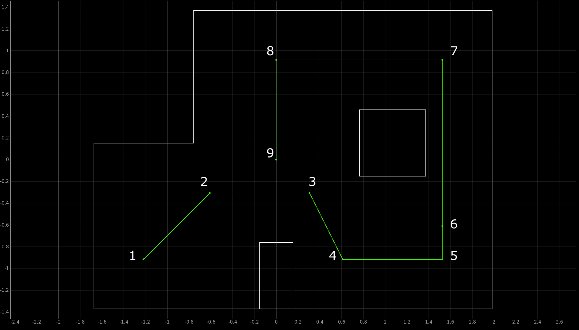
The instructions for this lab were very open-ended, meaning that we had to come up with our own strategy for navigating around the map. First, the map that we had to navigate the robot around was the same map used in labs 9-11. The waypoints to navigate around are shown in the picture below:

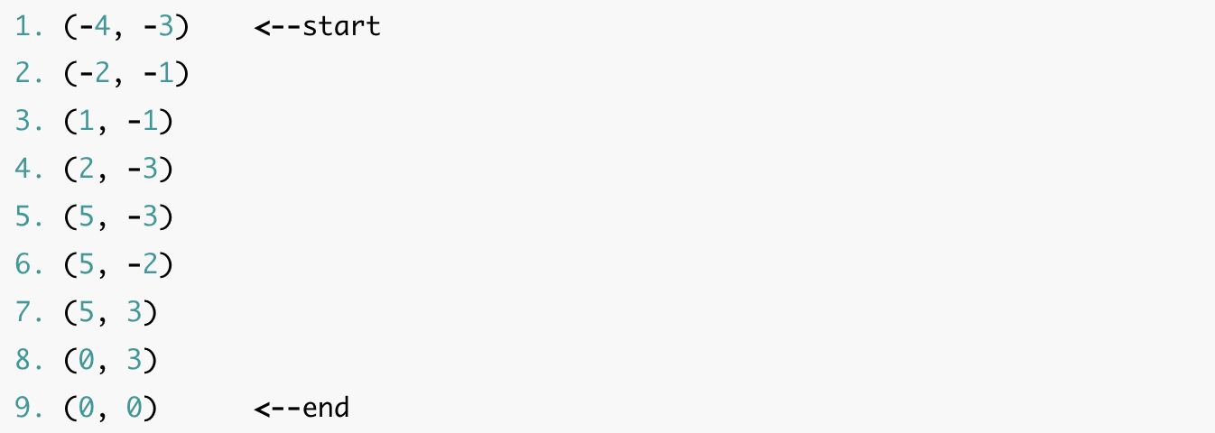
The exact coordinates (in feet) of the way points are:

The big picture strategy was as follow:
- Localize the robot
- Calculate the angle that the robot needs to turn by to face the next waypoint
- Calculate the distance the robot needs to travel to the next waypoint
- Rotate and then translate the robot
To achieve this, I defined 4 functions in Arduino (this was mostly just putting code from previous labs into separate functions):
- localize(): This function localizes the robot. Basically a copy-and-paste of the code from lab 11.
- pid_pos(setpoint_pos): This function implements PID position control. Stops the robot at a distance equal to setpoint_pos from the wall it's facing.
- pid_ori(setpoint_ori): This function implements PID orientation control. Rotates the robot by an angle equal to setpoint_ori.
- move_distance(dist): This function moves the robot by a distance equal to dist. If dist > 0, it moves the robot forward. If dist < 0, it moves the robot backward. This function makes use of the function pid_pos(setpoint_pos).
The code for the functions are below:
Testing Functions
The next step I took was to test these functions. Here are videos of the robot turning 120 degrees and 330 degrees using the pid_ori(setpoint_ori) function:
As you can see, the orientation control was very accurate.
Next, I tested the move_distance(dist) function. Here are videos of the robot moving 50 cm forward, 100 cm forward, 100 cm backward as marked by the green tape on the floor:
One observation I made was that as dist increases, the error (actual distance traveled - dist) increases. So I needed to adjust for this later when I executed the navigation task. Nonetheless, the position control was also very accurate. Also, there was no need to test pid_pos(setpoint_pos) separately because it's gets called in move_distance(dist) and because this function works pretty well, I knew that pid_pos(setpoint_pos) worked pretty well. Also, since I had completed localization for lab 11 just the week before (and it performed reasonably well), I didn't feel a need to test localize() and decided to move onto the next task.
Navigation Using PID Control
Before using localization to perform navitgation, I decided to try to navigate the waypoints using PID control only (i.e. using pid_ori and move_distance only). The robot would start facing rightwards. One immediate problem I ran into was that when the robot tried to get from the first waypoint to the second waypoint, the wall it was facing was about 3.4 m away. One of the issues with the TOF sensor on the robot is that it gives very unreliable readings when the distance it's measuring is very far (> 3 m). Because the TOF readings were quite inaccurate, this caused PID position control to be very inaccurate. When I consulted Anya with this issue, she suggested that I rotate my robot 180 degrees so that it was facing the wall behind it which was a lot closer (less than 1 meter). This was a really good idea and it worked. With that in mind, the algorithm for navigation using PID control is the following:
- 1→2: Turn 45 degrees, turn 180 degrees, go backwards 0.862104586 meters, turn 180 degrees
- 2→3: Turn 315, go straight 0.914 meters
- 3→4: Turn 310 degrees, go straight 0.682 meters
- 4→5: Turn 60 degrees, go straight 0.914 meters
- 5→6: Turn 90 degrees, go straight 0.305 meters
- 6→7: Go straight 1.524 meters
- 7→8: Turn 90 degrees, go straight 1.52 meters
- 8→9: Turn 90 degrees, go straight 0.914 meters
Algorithm translated into C++ code:
This method worked really well. I was able to get the robot to successfully navigate through the waypoints on the 3rd attempt. Having a robus PID controller (as shown in the previous videos) for both position and orientation made things a lot easier. The following is a video of a successful navigation attempt:
An honest note: I didn’t expect it to fully work the 3rd attempt so I didn’t record it from the start...In the next attempt, it worked up to the 4th waypoint but got stuck on one of the walls afterwards. So I merged the two videos together. But I swear it did naviagte successfully through all of the waypoints on the 3rd attempt!
Navigation Using Localization
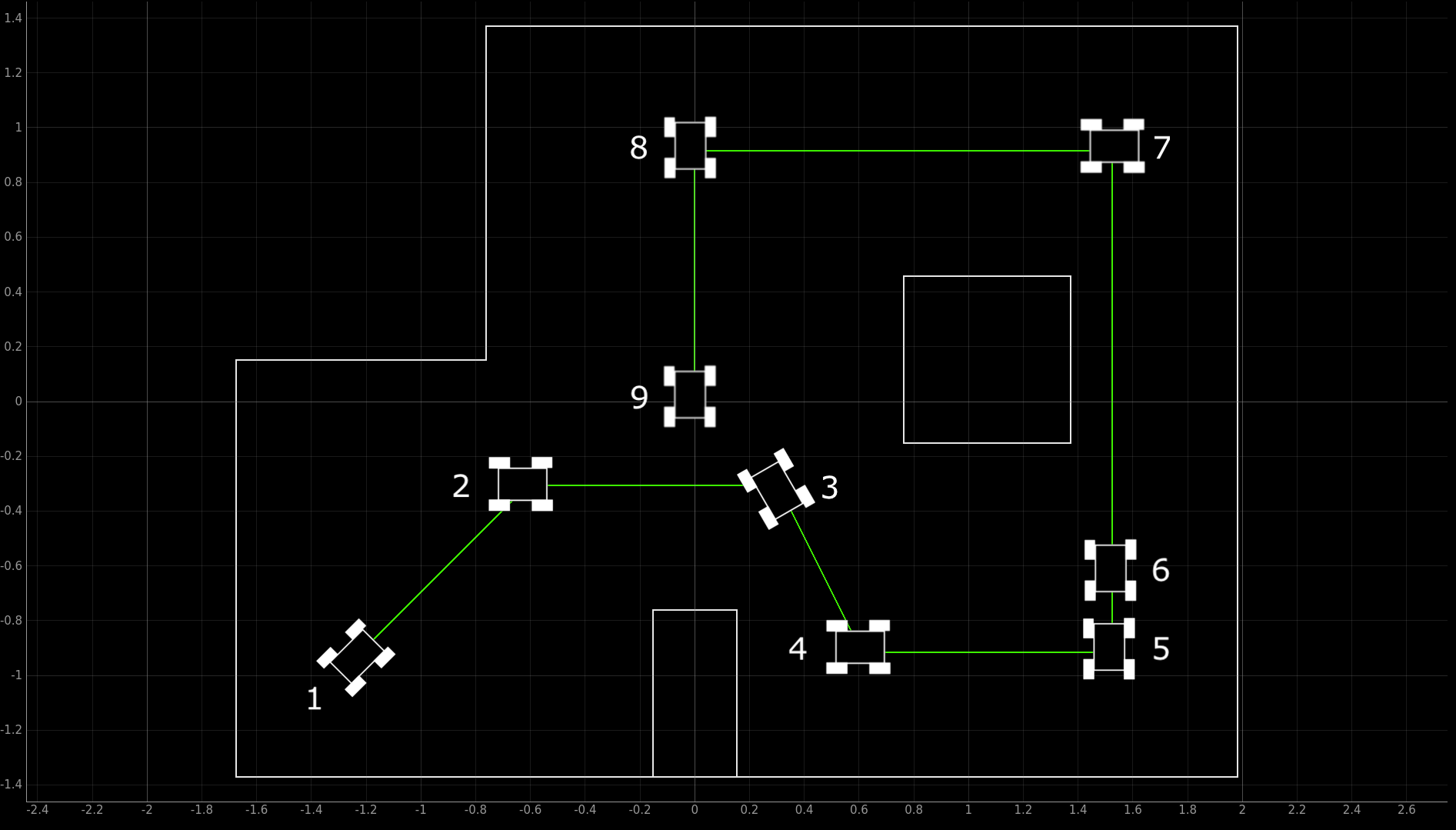
Now that I got things to work using just PID control, next, I wanted to try and get it to work using localization. First, I determined the desired poses at each of the waypoints:

The robot is at 0 degree angle when it points to the right. From the zero point, the angle becomes more positive in the counterclockwise direction and becomes more negative in the clockwise direction. So +90 degrees corresponds to the robot facing upwards and -90 degrees corresponds to the robot facing downwards. With that in mind, I created a list containing the desired poses at each of the waypoints:
- [-1.2192,-0.9144,45]
- [-0.6096,-0.3048,0]
- [0.3048,-0.3048,-60]
- [0.6096,-0.9144,0]
- [1.524,-0.9144,90]
- [1.524,-0.6096,90]
- [1.524,0.9144,180]
- [0,0.9144,-90]
- [0,0,-90]
The algorithm for navigation is as follows:
- Localize the robot: Command the robot to localize using the function localize(). Robot sends the sensor data back to the laptop. Compute the belief offboard on the laptop. If the belief matches the desired pose, grab the next desired pose from the list and repeat step (1). If not, execute the next steps.
- Compute the pose discrepancy: Compare the robot's belief to the desired pose and compute the distance discrepancy and angle discrepancy. Send this data to the robot.
- Translate & rotate the robot: Translate and rotate the robot by the amount calculated using the move_distance(dist) function and the pid_ori(setpoint_ori) function. Then return to step (1).
Translated into Python code:
Note that I had to set up commands LOCALIZE, MOVE_DISTANCE, ROTATE on the Arduino side so that the functions localize(), pid_ori(setpoint_ori), move_distance(dist) could be called from the laptop via BLE. The code for these commands is below:
Unfortunately, I could not get a successful run using localization. The problem I had was that I got very inaccurate localization beliefs. Nonetheless, I still learned much from trying to get navigation working using localization.
Unlike navigation using PID, using localization requires a lot of offboard computation which involves data to be sent back and forth between the robot and the laptop. This really made me realize the value of everything we did in lab 2. BLE is a powerful tool that allows all of the heavy data processing and computation to be done offboard by a device with more computational power than the Artemis microcontroller. The Artemis microcontroller did not do any heavy data processing during this lab - most of the code on the Artemis was just actuating commands (moving by a certain distance, rotating by a certian angle).
Another thing that I came to appreciate was the purpose of PID control. I realized that the entire point of using PID control is that it removes any trouble due to a lot of the changing external factors like changing battery levels, different friction coefficients for different floors, etc. The whole point of PID controller is that it accomodates for these changes (which could be considered a disturbance input) by varying the control input.
Conclusion
Overall, this lab was extremely rewarding despite the long hours in the lab. I learned so much from trying to put all the pieces together from the previous labs to get the robot to perform a complex task like navigation. Everything truly came together and made me appreciate all that we did in the previous labs. Many thanks to the course staff (Prof. Petersen and all of the TAs) and my peers for the wonderful learning experience this semester!