Localization Simulation
The main difference between this lab and lab 10 is that I used real data collected by the robot's sensors to perform localization. I used mostly code from lab 9 to perform the data collection (by spinning the robot in place adn collecting TOF data). Also, we were provided the code implement the Bayes filter. I first used the provided code to simulate the Bayes filter:

As explained in lab 10, the green trajectory is the ground truth trajectory. The blue trajectory is the trajectory according to the robot's belief. The red trajectory is the trajectory based on solely the odometry data.
Localization on Real Robot
The only function that I really had to implement was the perform_observation_loop function. This function performs the observation loop behavior on the real robot, where the robot does a 360 degree turn in place while collecting equidistant (in the angular space) sensor readings, with the first sensor reading taken at the robot's current heading. The number of sensor readings depends on "observations_count"(=18) defined in world.yaml. By default, observations_count is set to 18. This means that the robot should collect TOF data every 20 degrees.
My code from lab 9 was written to log a sensor measurement every 0.5 seconds. This was too sparse. That is, I couldn't get sensor readings that were exactly 20 degrees apart since it only logged the sensor data every 0.5 seconds. So I tweaked the Arduino code from lab 9 so that it logs the sensor data as frequently as it can and decided to process it off board afterwards (within the perform_observation_loop function). Here is the code I wrote for this function:
The variable 'array' in the code above is the raw time-stamped sensor data. The first 3000 elements of the array contain time-stamped yaw data and the next 3000 elements contain the time-stamped distance data.
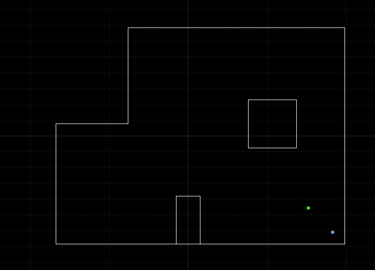
Just like in lab 9, I performed the observation loop at the 4 designated points in the map: (5,-3), (5,3), (0,3), and (-3,-2) where the units are in feet. Here is the result of running the Bayes filter algorithm on the observation loop data obtained at location (5,-3):

The belief (i.e. robot's "best guess" at where it was) was (1.829,-1.219,110.000). The ground truth is (1.524,-0.9144,90). This was not a bad result as it was only 1 foot off in each of the coordinate directions and 20 degrees off in orientation. Note that a 0 degree orientation corresponds the the robot's TOF sensor facing rightwards and it increases as the robot turns counterclockwise.
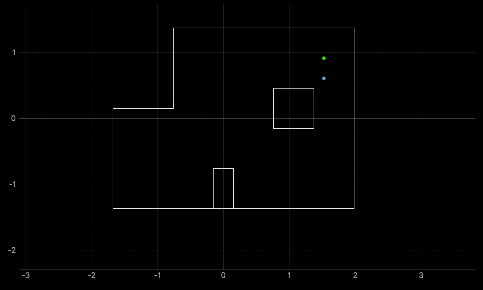
Here is the result of running the Bayes filter algorithm on the observation loop data obtained at location (5,3):

The belief of the robot at this location was (1.524, 0.610, 110.000). The ground truth is (1.524,0.9144,90).This is better than the belief at location (5,-3) as it was off by 1 foot only in the y-coordinate direction. But again, the orientation was off by 20 degrees.
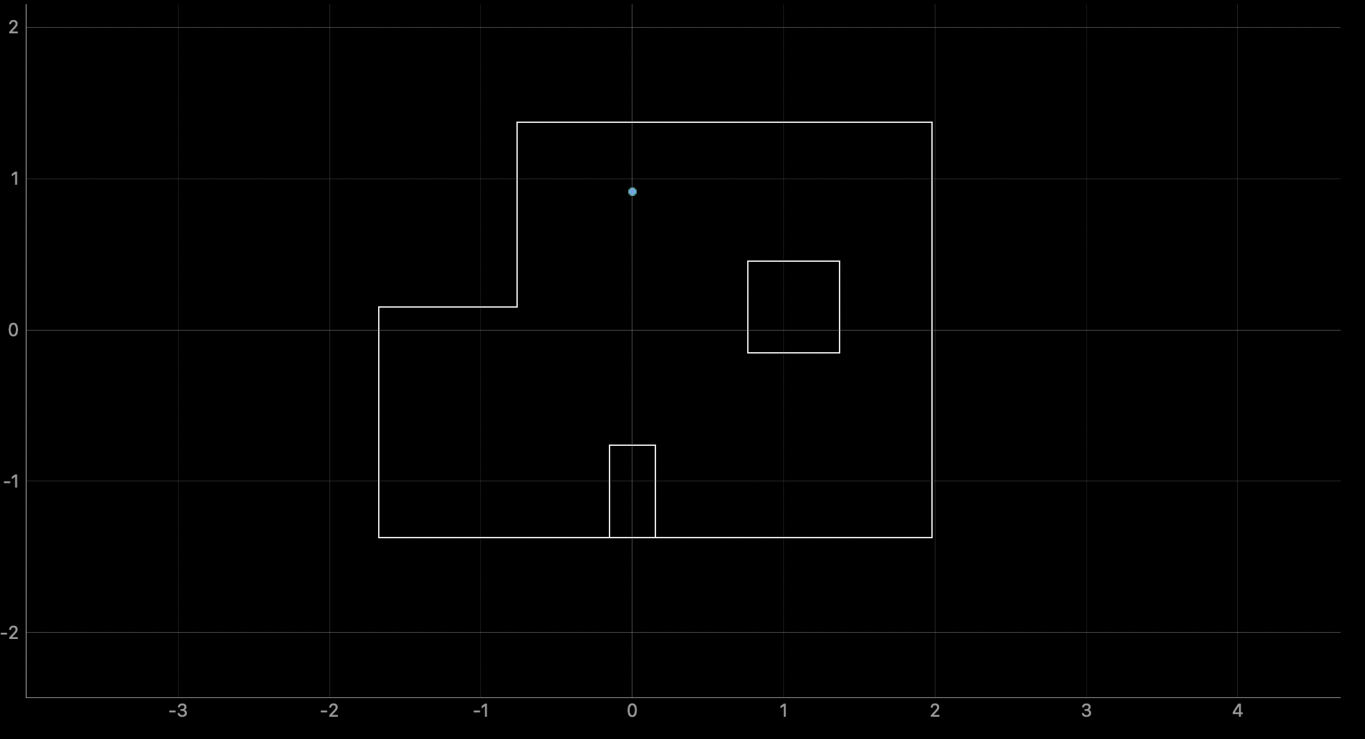
Here is the result of running the Bayes filter algorithm on the observation loop data obtained at location (0,3):

The belief of the robot at this location was (0.000, 0.914, 110.000). The ground truth is (0.000, 0.914, 90.000). The x and y coordinates of the blief exactly matched the ground truth (the green dot and blue dot coincide in the plot above) but the orientation is off by 20 degrees.
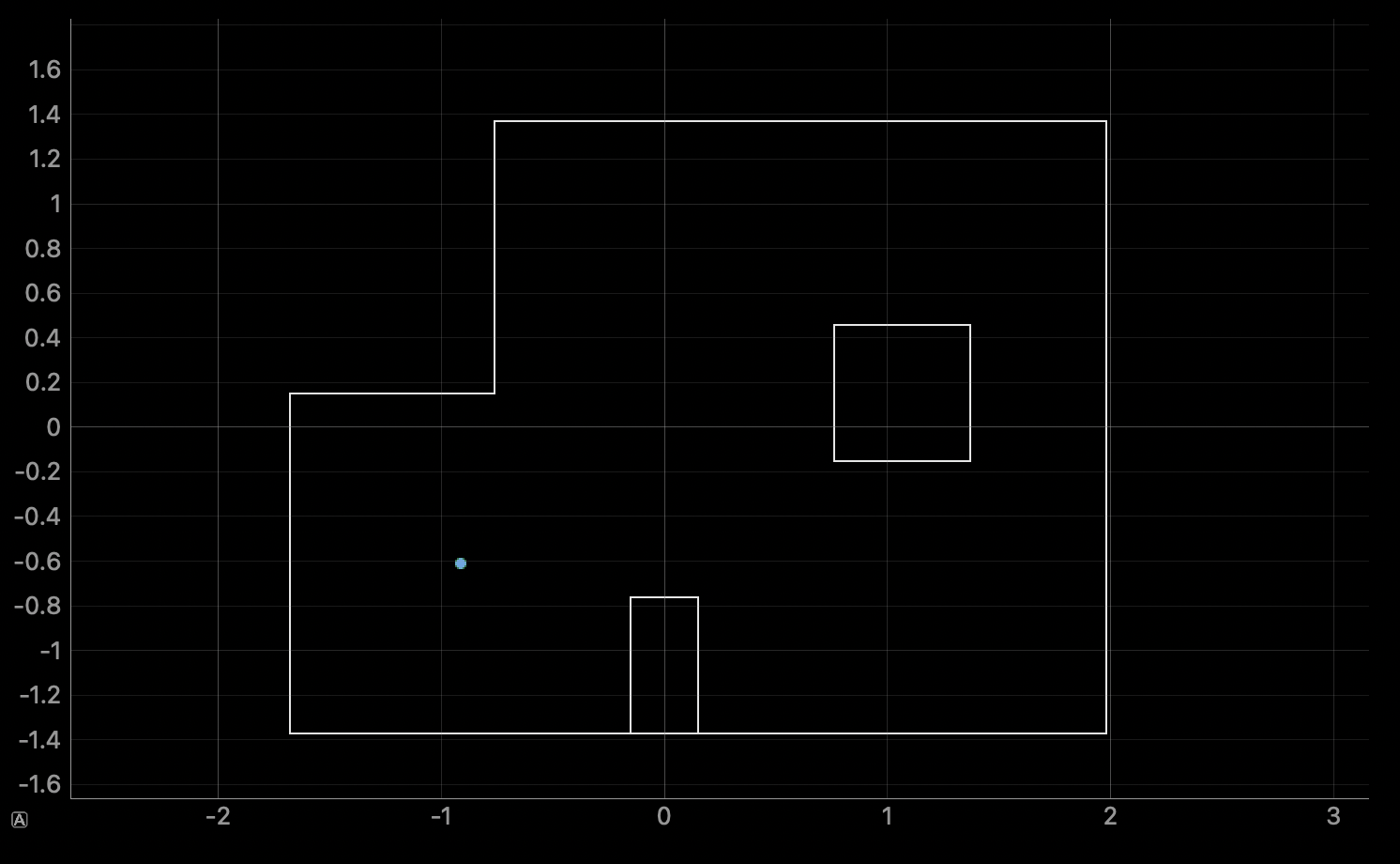
Finally, here is the result of running the Bayes filter algorithm on the observation loop data obtained at location (-3,-2):

The belief of the robot at this location was (-0.914, -0.610, 130.000). The ground truth is (-0.914, -0.610, 90.000). Again, the x and y coordinates exactly matched the ground truth but the orientation was off by 40 degrees this time.
Discussion
Overall, I thought that the localization for the x and y coordinates were quite accurate. Each direction was never off by more than 1 cell (i.e. 1 foot). However, there seems to be a consistent error in the orientation. For three of the four locations, the orientation was consistently off by 20 degrees (which corresponds to 1 cell in the discretized orientation space). And at the fourth location, it was off by 40 degrees (2 cells). It was hard to determine why it was consistently off but one possible solution to this is to introduce finer discretization. Instead of spacing apart the orientation space in 20 degree increments, I could try to space them apart by 10 degree increments. This was recommended to me by Lemon (TA) and I will try to implement this for lab 12.